Sizing tool + global sourcing guide · Reviewed
3 Stage Gearbox Manufacturer: Sizing & RFQ
Estimate your requirements below, export a brief, then compare documented manufacturer options. Preliminary calculations require supplier confirmation.
Request engineering review1. Four decisions before shortlisting a manufacturer
| Decision | Evidence or method | Next action |
|---|---|---|
| Confirm the stage count separately from ratio. | Ratios multiply; RV is documented as a two-stage alternative. | Nabtesco cycloidal engineering ↗ |
| Compare actual efficiency at the operating point. | The linked PLE catalog lists 92% for three stages; SEW states 96% gearing efficiency for three-stage R/F/K. Different scopes and products. | Neugart PLE technical catalog ↗; SEW R/F/K efficiency, edition 02/2026 ↗ |
| Keep a backlash target separate from evidence. | The tool illustrates propagation; no product tolerance is verified. | Ask for a complete gearbox test and test conditions. |
| Obtain dated commercial terms. | Prices, lead times, MOQ and model-specific approvals are unknown here. | Request comparable written quotations. |
Use the tool to prepare questions, then qualify an actual model. Published by LowBacklashGearbox, which receives engineering inquiries through this site. This guide is not an independent supplier ranking.
2. Calculation method, assumptions and limits
| Output | Reproducible method | Limit |
|---|---|---|
| Stage split | Planetary/helical: equal cube-root ratios. Bevel-helical: first ratio 3; divide the remaining ratio equally. | Ideal continuous numbers; no discrete tooth-count selection. |
| Speed and torque | n_out = n_in / i; T_out = T_in × i × η_total. | Calculated running torque is not a catalog rating. SF gives a selection requirement. |
| Power balance | P_in = T_in × n_in × 2π / 60000; P_out = P_in × η_total. | η_stage is an illustrative 0.97 planetary or 0.98 helical/bevel-helical; η_total = η_stage³. |
| Backlash | j_out = j1/(i2 × i3) + j2/i3 + j3. | Stage OUTPUT play assumptions: 3 arcmin planetary, 12 helical or 8 bevel-helical. No measurement or compliance prediction. |
| Inertia | J_ref = J_load/i²; ratio = J_ref/J_motor. | Omits gearbox inertia, stiffness, controller and motion-profile limits. |
| Thermal sensitivity | A = P_loss × 1000 / [10 × (80 − ambient °C)]. | Ideal convection-only area in m²; assumed h=10 W/(m² K), 80°C case. No casing sizing, cooling approval or ISO thermal rating. |
The tool validates every numeric input before displaying results or enabling export. The on-screen bounds define this tool’s scope, not a manufacturer’s allowable operating envelope. Defaults are examples. No strength, bearing-life or safety function is calculated.
3. Ratios multiply; stage count is a separate specification
A 4 × 5 × 5 split is one mathematical way to obtain 100:1. The tool instead starts with equal cube-root ratios unless a bevel stage is selected. Neither split proves that suitable teeth, bearing sizes or an off-the-shelf product exist. Require a drawing and catalog code identifying all three stages.
4. Separate running torque, selection torque and peak loads
At 100:1, 8.5 Nm input and 0.97³ assumed efficiency give about 775.77 Nm running output torque. A 1.35 service factor gives a 1047.29 Nm selection requirement. These calculations do not increase the mechanical capacity of a gearbox.
Obtain continuous, permitted acceleration and emergency-stop ratings independently. Include cycle counts, duration, external shaft loads and motor braking behavior. Use the supplier’s load spectrum assessment for variable duty, rather than choosing an arbitrary peak multiplier.
5. Backlash propagation is a model, not a pass certificate
| Stage | Division to final output | Contribution (arcmin) |
|---|---|---|
| 1 | 5 × 5 | 0.12 |
| 2 | 5 | 0.60 |
| 3 | 1 | 3.00 |
| Total | Sum of contributions | 3.72 |
Under these assumptions the final stage contributes about 81% of the output play. This percentage changes with stage ratios and actual stage play. Lowering a target in the tool cannot prove that the assembled gearbox meets it.
Specify whether acceptance covers unloaded backlash, hysteresis or loaded lost motion; agree the input lock, applied torque, temperature and measurement procedure. Elastic deflection requires stiffness data in addition to backlash.
6. Load sharing and gear strength need the actual geometry
Request the manufacturer’s tooth-load and load-sharing assessment for its carrier, pins, bearings and gear geometry. A fixed relationship between pin position error and K_gamma is not established here; a generic tolerance cannot justify a universal load factor.
ISO 6336-1:2019 ↗ provides the general spur/helical load-capacity framework. We verified the public scope, not a clause-by-clause calculation. The calculator does not implement ISO 6336 or certify a strength margin.
7. Bearing rating life requires load and relative speed
For a roller bearing at constant equivalent load, L10h = 10⁶/(60 × |n_rel|) × (C/P)^(10/3), with C and P in the same force units. L10 is a statistical fatigue rating at 90% reliability, rather than a guaranteed maintenance interval. SKF: bearing life equations and limits ↗
| Assumed C / P | |n_rel| (RPM) | Calculated L10h (hours, rounded) |
|---|---|---|
| 8.9 kN / 0.620 kN | 480 | 249,614 |
| 18.5 kN / 3.1 kN | 96 | 66,928 |
Use absolute relative bearing speed, actual bearing capacity and equivalent load including the load distribution. Lubrication, contamination, mounting and raceway suitability still require review. ISO 281:2007 ↗ defines the rating-life scope; the tool above does not calculate bearing life.
8. Compare architectures on the same duty
| Architecture | Reason to investigate | Critical comparison |
|---|---|---|
| Planetary | Coaxial package and shared planet loading. | Actual backlash, output bearings, speed and heat at your duty. |
| Helical | Industrial parallel or inline layouts. | Housing footprint, shaft loads and configured ratio. |
| Bevel-helical | A right-angle mounting requirement. | Bevel stage geometry, shaft direction and installation space. |
| Cycloidal | An alternative for joint stiffness and shock-loading requirements. | Use the complete supplier model; RV is described as two-stage. Nabtesco cycloidal engineering ↗ |
These are screening questions. Do not transfer a backlash class, overload factor or efficiency from one family to another. A lower-stage-count unit may fit the requested duty with less length and fewer components; request a comparable alternative quote.
9. Check heat loss against configured thermal capacity
At the default operating point, input power is about 2.670 kW. The 0.97³ assumption gives about 0.233 kW heat loss. The tool’s area is only a sensitivity scenario for an assumed 80°C casing in still air; radiation, mounting conduction, oil circulation and temperature-dependent losses are omitted.
ISO/TR 14179-1:2001 ↗ uses a mineral-oil heat balance with reference conditions of 25°C maximum ambient and 95°C sump temperature, plus modifiers. Casing temperature and sump temperature are different quantities. Our simplified area calculation does not implement that standard.
There is no universal 2.5 kW threshold that mandates a fan or a particular lubricant. Ask for the thermal rating at your mounting, ambient temperature, input speed and duty cycle. Compare larger frames, revised duty or supplier-approved cooling if the requirement exceeds that rating.
10. Manufacturer landscape: documented options and unknowns
Evidence snapshot checked on 28 October 2026. This is a starting list, with no ranking or endorsement. Public documentation establishes architecture, not availability for your application.
| Manufacturer / family | Public evidence | What to request |
|---|---|---|
| Neugart / PLE | Catalog tables contain a three-stage row with frame- and ratio-specific ratings. Neugart PLE technical catalog ↗ | Configured ratio, frame, backlash and input speed; latest datasheet revision. |
| SEW-EURODRIVE / R | Official product page explicitly includes two- and three-stage R units. SEW R series product documentation ↗ | Exact model and stage count, output shaft loads, thermal data. |
| Sumitomo / PARAMAX 9000 | Official range documentation lists triple reduction among its available architectures. Sumitomo PARAMAX industrial gearbox documentation ↗ | Arrangement, frame, current ratio and lubrication instructions. |
| Nabtesco / RV — alternative | Manufacturer describes a two-stage cycloidal mechanism. Nabtesco cycloidal engineering ↗ | Compare the complete reducer; do not assume three stages. |
| LowBacklashGearbox — site publisher | Engineering inquiry available through our contact form. No model-specific public test report is supplied here. | Signed drawing, architecture, measured ratings, inspection scope and dated offer. |
Price, lead time, MOQ and application-specific certifications: not verified for every row. Obtain them in writing. The linked sources do not establish that all products in a family share one stage count or one precision class.
11. Inspection evidence and lubricant selection
ISO 1328-1:2013 ↗ classifies individual cylindrical gear flank deviations. Request the actual diameter, module, tolerance class and inspection record; there is no universal micrometre tolerance or assembled backlash implied by “Grade 5/6”.
Specify assembled output backlash, torsional stiffness, noise test conditions and shaft-interface inspection separately. Agree whether material certificates, heat-treatment records and gear inspection traces are needed for the supplied serial numbers. A material certificate alone does not establish case depth or completed assembly performance.
Follow the selected unit’s approved lubricant and mounting instructions. Do not infer grease grade, oil viscosity, replacement interval or compatibility from stage count. Confirm ambient range, duty, seal materials, fill quantity and permitted relubrication with the manufacturer.
12. Three worked RFQ scenarios
Illustrative calculations using the tool’s presets; these are not customer projects, qualification tests or delivery results. Reload a named preset above to reproduce the values.
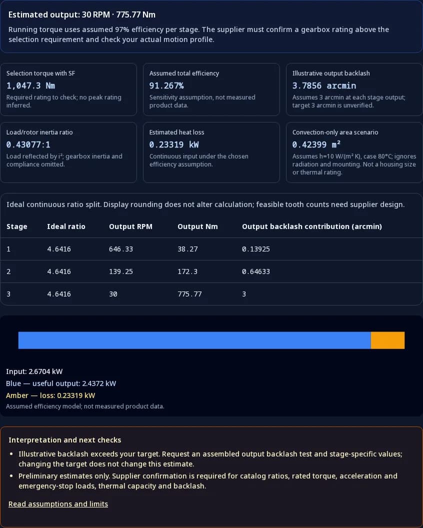
Servo indexer
Assumptions: 100:1, 3000 RPM, 8.5 Nm; SF 1.35.
30.00 RPM · 775.77 Nm
Selection requirement: 1047.29 Nm; estimated loss 0.233 kW.
Next: verify continuous and peak ratings, output bearing loads and thermal duty; request a measured backlash result against the target.
Conveyor
Assumptions: 64:1, 1500 RPM, 35 Nm; SF 1.75.
23.44 RPM · 2108.27 Nm
Selection requirement: 3689.47 Nm; estimated loss 0.323 kW.
Next: verify continuous and peak ratings, output bearing loads and thermal duty; request a measured backlash result against the target.
Right-angle drive
Assumptions: 40:1, 4000 RPM, 4.2 Nm; SF 1.5.
100.00 RPM · 158.12 Nm
Selection requirement: 237.18 Nm; estimated loss 0.103 kW.
Next: verify continuous and peak ratings, output bearing loads and thermal duty; request a measured backlash result against the target.
13. RFQ checklist, costs and application risks
| Risk | Missing evidence | Mitigation or alternative |
|---|---|---|
| Undersized drive | Acceleration, braking and external shaft loads. | Provide a motion profile and load spectrum; compare supplier continuous and transient ratings. |
| Precision mismatch | Assembled backlash and stiffness under specified conditions. | Agree acceptance tests; compare another frame or architecture if necessary. |
| Unexpected cost | Interfaces, sample tooling, inspection, shipping and repeat quantities. | Request an itemized quote and a comparable standard-model option; do not assume a fixed three-stage premium. |
| Thermal or lubrication mismatch | Ambient, enclosure, mounting and actual efficiency. | Request a configured thermal assessment; compare duty changes, frame changes or approved cooling. |
| Delivery or qualification gap | Dated schedule, serial-number reports and revision control. | Approve a representative sample before a volume order; verify certificates for the supplied model and scope. |
Send the exported brief with the motor drawing, cycle timing, output load spectrum, shaft forces, available envelope, environmental requirements and target service life. Incomplete duty data means final selection remains pending.
Request a 3-stage gearbox engineering review14. Engineering and sourcing FAQ
Sizing and architecture
Does 3 stage mean a 3:1 gearbox?
No. Three stages describes three successive reductions. Their ratios multiply: 4 × 5 × 5 gives 100:1. A 3:1 gearbox specifies the total ratio and can use a single stage.
When should I compare two stages with three?
Compare available catalog ratios, continuous torque, permissible input speed, efficiency, axial length and price for the same duty. A high ratio does not by itself prove that three stages is best.
Are the proposed stage splits manufacturable?
They are continuous mathematical splits, not tooth-count designs. The manufacturer must check tooth counts, undercut, assembly geometry, contact ratio and the available catalog ratio before confirming a build.
Is a cycloidal reducer always a three-stage option?
No. Nabtesco describes its RV design as two-stage. Compare a complete cycloidal reducer using its own datasheet; do not model its mechanism as three identical planetary stages.
Precision and ratings
Does selecting a tighter backlash target improve the output estimate?
No. The target is a procurement requirement. This model uses an independent illustrative stage-play assumption; only measured stage or assembled gearbox data can establish whether a real product meets the target.
Does a service factor establish peak output torque?
No. Multiplying estimated running torque by a service factor gives a selection requirement. Acceleration, shock and emergency-stop loads need separate motion-profile calculations and the supplier’s permitted peak ratings.
Does ISO 1328 Grade 5 or 6 guarantee low assembled backlash?
No. Gear flank tolerance and assembled backlash are separate acceptance criteria. Specify the component accuracy scope and request an output backlash test with defined torque, temperature and input-lock conditions.
Can I use the reflected inertia ratio as a servo stability guarantee?
No. Load inertia is divided by ratio squared, but the complete system also includes rotor and gearbox inertia, shaft stiffness, couplings and the controller. Check the drive manufacturer’s limits and tune the assembled axis.
Heat and procurement
Are efficiency and thermal capacity verified by this calculator?
No. Efficiency is a stated scenario assumption. Heat loss follows from that assumption. The convection-only area uses an assumed coefficient and case temperature; it does not establish housing dimensions or continuous thermal capacity.
Which lubricant should a three-stage unit use?
Use the configured reducer’s approved lubricant, viscosity or grease grade, fill quantity and mounting instructions. Stage count alone cannot determine compatibility, a maintenance interval or a lubricant change.
What are current price, MOQ and lead time?
They are not verified on this page. Obtain dated quotations for the same model, drawing revision, quantity, inspection scope, delivery location and shipping terms. Compare sample and repeat-order schedules separately.
What should I send after exporting the brief?
Add the motor drawing, mounting envelope, continuous and peak load profile, cycle duration, external shaft loads, target life and required inspection reports. Copy or download the brief and attach it to an engineering inquiry.
15. Sources, scope and verification date
Public sources checked on . Standards summaries use public abstracts; the full standards and a supplier calculation are needed for compliance work. Catalog documents are snapshots, so confirm the revision with the manufacturer. No proprietary test protocols or unshared project results are used as evidence.
- Neugart PLE technical catalog ↗
Pages 20–22: stage-specific efficiency, backlash and torque tables. Values depend on frame and ratio; confirm the current configured data.
- SEW R series product documentation ↗
Documents R series two- and three-stage configurations; series-wide ranges do not identify an individual three-stage unit.
- SEW R/F/K efficiency, edition 02/2026 ↗
Reports 96% gearing efficiency for three-stage R/F/K units. This is not a universal whole-drive efficiency guarantee.
- Sumitomo PARAMAX industrial gearbox documentation ↗
Official range overview lists double, triple and quadruple reduction. Request the current 9000-series model drawing, frame and ratio; the overview does not establish every configuration.
- Nabtesco cycloidal engineering ↗
Describes RV as a two-stage mechanism. Listed here as an alternative architecture, not evidence of a three-stage catalog product.
- ISO 6336-1:2019 ↗
Load-capacity framework for spur and helical gears; this tool does not calculate tooth strength or a mesh load-sharing factor.
- ISO 1328-1:2013 ↗
Cylindrical involute gear flank tolerance classification. A grade alone does not certify assembled reducer backlash.
- ISO 281:2007 ↗
Dynamic bearing ratings and rating life. Recheck the edition for procurement; ISO lists a revision in progress.
- SKF: bearing life equations and limits ↗
Explains C/P life exponents and the difference between basic rating life and application service life.
- ISO/TR 14179-1:2001 ↗
Analytical thermal rating for mineral-oil gear drives under stated reference conditions; distinct from the tool’s simple convection scenario.