Planetary vs. Harmonic vs. Cycloidal Reducers: A Sourcing and Engineering Decision Framework
Compare planetary vs harmonic vs cycloidal reducers for low backlash gearboxes. Check torque, lost motion, thermal limits, and sourcing risks before sending an RFQ.
Selection answer: When comparing planetary vs harmonic vs cycloidal reducers for low backlash gearboxes, shortlist planetary designs for efficient servo transmission, strain wave designs for compact high-ratio joints, and cycloidal designs for demanding torque and moment loads. Then qualify the exact model against loaded positioning error, duty cycle, emergency-stop torque, bearing loads, and delivered cost. No architecture wins every axis, and zero backlash does not mean zero deflection.
Published and technically reviewed: October 26, 2026. This is a global, English-language selection framework. Prices, availability, and delivery terms require a dated supplier quotation for the destination market.
Scope and limits: This guide supports mechanical engineers and procurement leads shortlisting precision servo-grade reducers for robotics, AGV/AMR traction, CNC feed axes, and packaging machines. It excludes hobby gearing, worm gearboxes, and large mill drives. The comparison uses the published sources below and engineering screening calculations; it is not a bench test, a supplier quotation, or approval of a particular machine design. Manufacturer claims apply to the cited product families and conditions.
Already have an axis specification? Send the motor model, load profile, and target ratio for an application review, or use the checklist below to prepare the missing inputs.
1. Start with the Axis Requirements
Engineering and purchasing teams need a common acceptance specification. Record output torque and speed over time, reversal frequency, payload lever arm, allowable positioning error, ambient temperature, mounting envelope, and annual quantity before comparing reducers.
An architecture label does not establish continuous torque, thermal capacity, fatigue life, or interchangeability. Oberneder et al.'s comparison of robot gearbox properties evaluates manufacturer specification data and shows why size and operating conditions matter; it is not a controlled endurance test of every gearbox family.
To build reliable machines within budget, procurement and engineering must evaluate the three foundational precision speed reducer architectures on equal technical footing:
- Precision Epicyclic Planetary Gearboxes
- Strain Wave (Harmonic) Gear Reducers
- Cycloidal (RV / Trochoidal) Reducers
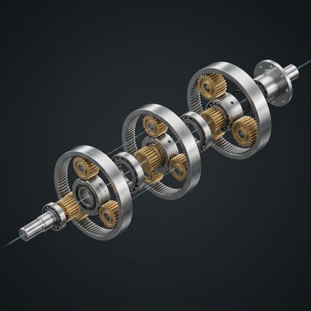
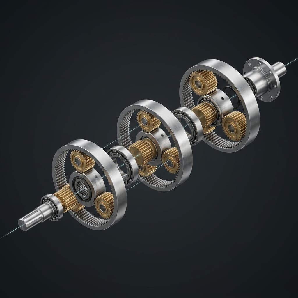
Visuals are explanatory illustrations, not dimensioned assembly drawings or evidence of measured performance.
2. Mechanical Architecture & Operating Principles
Each reducer architecture achieves speed reduction and torque multiplication through entirely distinct kinematic mechanics. Understanding these mechanical fundamentals reveals why each technology behaves differently under shock, speed, and thermal stress.
1. Planetary Gearboxes: Epicyclic Load Sharing
In a precision inline planetary gearbox, a central sun drives planet gears carried inside a ring gear. With the ring fixed, the carrier provides the reduced-speed output. Multiple planets can share the transmitted load, but manufacturing accuracy and assembly determine how evenly it is shared.
Involute teeth experience both rolling and sliding contact. Lubrication, seals, bearings, ratio, and speed all contribute to losses; helical teeth do not eliminate friction or wear. A helical planetary gearbox is a candidate when smooth engagement matters, subject to its axial bearing loads and duty rating.
2. Strain Wave Reducers: Flexspline Deformation
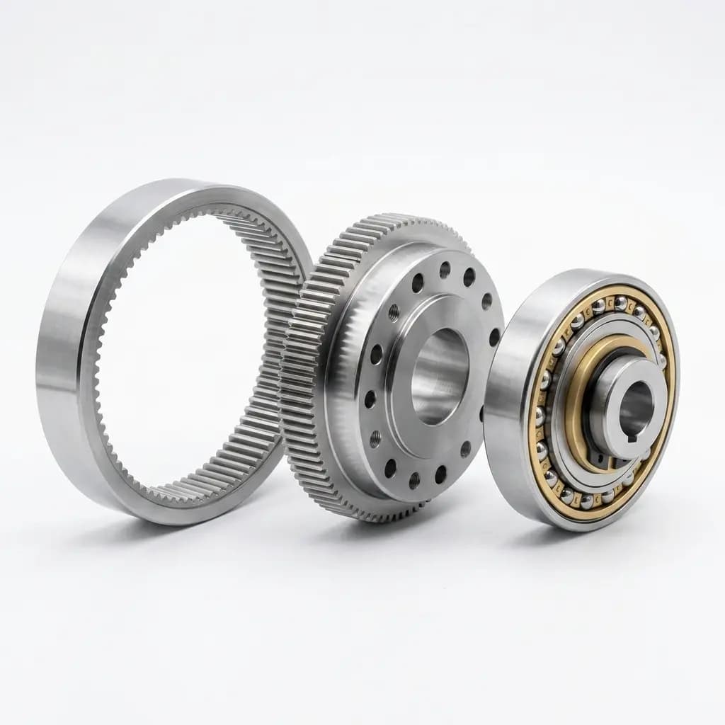
A common strain wave design has an elliptical wave generator, a flexible externally toothed flexspline, and a rigid internally toothed circular spline. The tooth-count difference produces a high reduction ratio as the wave generator rotates. Designs and tooth counts vary by series.
Zero-backlash meshing is valuable in compact joints. It does not eliminate elastic twist, hysteresis, transmission error, or bearing deflection under load. Compare a complete gearhead with another complete gearhead: a bare component set may still need an output bearing, housing, seals, and assembly work.
3. Cycloidal Reducers: Eccentric Disc and Pin Engagement
An eccentric input drives a lobed disc against a ring of pins or rollers; output pins transfer the reduced rotation. Some designs use paired discs to balance forces. An RV-type reducer may combine a preliminary gear stage with a cycloidal stage, so “RV,” “single-stage cycloidal,” and “all cycloidal reducers” are not interchangeable specifications. Sumitomo's single-stage and multi-stage guide illustrates why stage configuration needs checking.
3. The Five Core Engineering Trade-offs
Trade-off 1: Repeated Peak Torque vs. Emergency-Stop Torque
Separate continuous/rated torque, repeated acceleration torque, and occasional emergency-stop torque. The permitted duration and event count matter as much as the peak value. Do not apply a universal overload multiplier to an entire architecture.
Nabtesco's comparison describes substantial overload capacity for both its cycloidal and strain wave products. That does not establish a rating for another supplier's reducer. Request the selected model's torque limits, cycle assumptions, and inspection instructions after an overload.
For an initial output-side estimate, use load inertia × angular deceleration plus the signed external load torque, keeping every inertia and torque on the same shaft reference. Include gravity where relevant. Backlash impact, structural compliance, control response, and braking dynamics require further analysis; the simple estimate alone cannot approve an emergency stop.
Trade-off 2: Input Speed and Thermal Management
Check continuous or average input-speed limits separately from intermittent maximum speed. A permissible peak RPM does not establish continuous-duty capability. Request efficiency or loss-torque data at the actual speed, torque, lubricant temperature, and mounting conditions for every candidate.
For example, the Harmonic Drive HPG wheel-drive white paper reports 90–95% efficiency at rated input torque and speed for that planetary design. HPG is a planetary product family from Harmonic Drive, not evidence of strain wave efficiency or a universal planetary rating.
Illustrative heat calculation, not a product test: at 300 W mechanical output, estimated gearbox loss is P_loss = P_out × (1/η − 1). Assumed efficiencies of 95% and 80% give approximately 15.8 W and 75 W of loss respectively. Those assumed values show why the duty point matters; they do not rank actual reducers or predict housing temperature without a thermal model.
Trade-off 3: Ratio, Stage Count, and Complete Assembly Envelope
Start with ratio = motor speed / required output speed, then check available catalogue ratios. Planetary designs commonly serve lower-ratio servo axes and use multiple stages for higher reductions. Strain wave designs offer compact high-ratio arrangements. Cycloidal assemblies can use a single cycloidal stage or compound gearing.
Compare the complete installed length, diameter, mass, output bearing, motor adapter, cable clearance, and any hollow-shaft requirement. Do not compare a bare strain wave component set with a fully housed planetary gearbox and treat the size difference as an equal-scope result.
Trade-off 4: Backlash, Lost Motion, and Loaded Positioning Error
Backlash is clearance on reversal; hysteresis/lost motion also reflects load-dependent behavior. Suppliers may use different measurement torques and definitions. Torsional stiffness describes twist under load and can be nonlinear. Motor-side encoder resolution alone cannot observe output-side backlash or compliance.
Reproducible screening example: assume a 100 mm payload radius and 3 arc-minutes of angular clearance. The small-angle displacement is:
Linear displacement (mm) = radius (mm) × angle (arc-min) × π / 10800
100 × 3 × π / 10800 = 0.0873 mm
500 × 3 × π / 10800 = 0.4363 mm
At a 100 mm radius, an assumed 0.020 mm reversal-error allowance permits only about 0.688 arc-minutes for that error term. A 3 arc-minute candidate fails that clearance allowance before bearing or structural effects are considered.
A zero-backlash alternative still needs a stiffness check. With an assumed local stiffness of 20 Nm/arc-min at an applied 40 Nm, the linear approximation gives 2 arc-minutes of twist, or 0.0582 mm at a 100 mm radius. This also exceeds 0.020 mm. Use the actual torque–deflection curve and allocate separate error terms; these examples are not measured accuracy or repeatability results.
Trade-off 5: Backdrivability and Holding Requirements
Backdriving depends on ratio, preload, lubricant, seals, temperature, and motor drag. Obtain breakaway and running backdrive torque for the complete assembly. Forward efficiency alone cannot establish reverse efficiency or force-sensing accuracy.
For a vertical axis, do not assume any of these reducer types is self-locking or provides a holding brake. Evaluate holding and stopping functions at machine level. Likewise, a backdrivable reducer does not by itself establish collaborative robot safety or remove the need to validate force sensing.
4. Commercial & Sourcing Reality: Compare Equal RFQ Scope
There is no verified global price or lead-time dataset behind this article. Compare dated quotations for the same torque profile, ratio, complete assembly scope, quantity, delivery destination, and acceptance requirements. The table below defines what procurement should ask rather than assigning unsupported market averages.
| Sourcing parameter | Precision planetary | Strain wave (harmonic) | Precision cycloidal |
|---|---|---|---|
| Quoted assembly scope | Gearhead, motor adapter, coupling, output format | Component set or complete gearhead; identify bearing and housing scope | Component set or complete reducer; identify preliminary stage and bearing scope |
| Unit and integration cost | Quote the required backlash class and adapter | Include housing, output bearing, assembly, and validation if separate | Include output support, input drive, seals, and installation work |
| Sample vs. production lead time | Confirm stock by exact ratio and interface | Confirm allocation for the exact size and configuration | Confirm build slot and any custom machining |
| Second-source qualification | Match drawings, ratings, and test definitions | Match component geometry, bearing support, and preload requirements | Match bolt pattern, input arrangement, lubrication, and load ratings |
| Motor mounting | Confirm pilot, shaft, clamp, and insertion depth | Confirm wave-generator or gearhead input interface | Confirm input coupling or pinion arrangement |
| Lubrication and maintenance | Use the selected model's lubricant, life assumptions, and orientation limits | Obtain lubricant quantity, replacement instructions, and life conditions | Confirm oil/grease choice, fill quantity, mounting orientation, and service access |
| Delivered cost and spares | Include freight, destination charges, adapters, and spare stock | Include integration fixtures and replacement assembly scope | Include service tooling and replacement installation scope |
Supply Chain Lock-In: Qualify the Interface, Not the Label
A standard keyway, spline, or flange feature does not make the whole gearbox interchangeable. Across all three architectures, compare pilot fits, bolt circles, shaft engagement, overall length, bearing loads, stiffness, lubricant requirements, and torque ratings. Record drawing revisions and agree on the acceptance test before approving a second source.
If a planetary design meets the error budget, compare inline mounting options and right-angle packaging against the available envelope. A right-angle stage can change losses and ratings; verify the complete assembly.
For total cost of ownership, add purchase, adapters and bearings, integration/qualification, maintenance, energy, and spare inventory using the same service period. Keep quoted facts separate from assumed downtime or energy costs. Ask suppliers to state quotation validity and sample/production delivery terms explicitly.
5. Comprehensive Reducer Comparison Matrix
These are shortlisting tendencies, not guaranteed ratings. Nabtesco's published comparison supports compact strain wave and high-load cycloidal use cases for its own ranges; the selected model's documentation must resolve every acceptance criterion below.
| Engineering & sourcing metric | Precision planetary gearbox | Strain wave (harmonic) drive | Cycloidal reducer |
|---|---|---|---|
| Operating principle | Sun, planets, ring, and carrier | Flexspline deformation and tooth-count difference | Eccentric disc engaging pins or rollers |
| Ratio and stages | Check ratio and number of planetary stages | Check available ratio and component/gearhead format | Check cycloidal and preliminary-stage configuration |
| Reversal behavior | Specify backlash class and measurement torque | Zero-backlash designs still have hysteresis and compliance | Specify backlash and lost-motion definitions separately |
| Loaded positioning | Use torque–deflection and bearing data | Use torque–deflection and bearing data | Use torque–deflection and bearing data |
| Shock approval | Model-specific peak, duration, and event count | Model-specific peak, duration, and event count | Model-specific peak, duration, and event count |
| Input-speed approval | Separate continuous/average and peak RPM | Separate continuous/average and peak RPM | Separate continuous/average and peak RPM |
| Efficiency and heating | Obtain duty-point curves or loss data | Obtain duty-point curves or loss data | Obtain duty-point curves or loss data |
| Packaging emphasis | Coaxial or right-angle housed arrangements | Compact high-ratio joints; check complete bearing scope | High-torque assemblies; check complete stage scope |
| Backdriving | Measure complete-assembly breakaway torque | Measure complete-assembly breakaway torque | Measure complete-assembly breakaway torque |
| Noise comparison | Require speed, load, distance, and test conditions | Require speed, load, distance, and test conditions | Require speed, load, distance, and test conditions |
| External loads | Verify radial/axial load and moment limits | Verify whether output bearings are included | Verify radial/axial load and moment limits |
| Commercial acceptance | Dated, equal-scope quote and interface approval | Dated, equal-scope quote and interface approval | Dated, equal-scope quote and interface approval |
6. Application Decision Framework: Build a Shortlist, Then Qualify It
- High-speed packaging, gantries, or traction axes: shortlist planetary gearheads when the available ratio and efficiency curves suit the motor operating point. Check wheel or pulley bearing loads, reversal error, and continuous thermal conditions.
- Compact robot wrists, optical positioners, or lightweight joints: shortlist strain wave designs when high ratio and low clearance fit the envelope. Check loaded deflection, input losses, external bearing requirements, and overload life. Cleanroom or medical suitability requires separate product evidence.
- High-torque robot bases, indexers, or large moment loads: shortlist precision cycloidal assemblies. Confirm bearing moment capacity, lost motion, full assembly mass, lubrication, and emergency-stop ratings instead of assuming unlimited shock resistance.
Decision rule: reject a candidate that misses an essential load, thermal, interface, or positioning requirement before comparing price. When two architectures pass, compare their complete installed cost and qualification risk. A change in reducer type usually requires mechanical and control validation.
7. Engineering & Sourcing Checklist
Use this checklist as the RFQ handoff and release record:
- Duty profile: supply torque and speed versus time, reversals, ambient temperature, mounting orientation, and required service life. Obtain thermal and lubrication limits for those conditions.
- Emergency stop: document output-side inertia, external load torque, deceleration time, and anticipated stop count. Compare calculated and validated loads with the model's permitted peak duration and event count.
- Input speed: check both continuous/average and intermittent limits at the required ratio. Request derating conditions rather than accepting a single maximum-RPM figure.
- Positioning error: state payload radius, allowable reversal error, measurement torque, loaded stiffness, and feedback location. Use the calculation in Section 3; do not equate encoder resolution with tool-point accuracy.
- Bearing and interface loads: check radial/axial loads, overhung distance, tilting moment, motor pilot, shaft engagement, and bolt pattern. Request an output-bearing and mounting review where support is uncertain.
- Supply and second source: obtain exact part numbers, drawing revisions, quote validity, sample/production delivery dates, and destination terms. Approve an alternate through drawing and performance checks.
- Total installed cost: include adapter, bearings, housing, lubrication, integration, validation, service access, and spares. Record assumptions separately from supplier commitments.
8. Frequently Asked Questions (FAQ)
Q1: Can a planetary gearbox replace a harmonic drive in a robot joint?
Possibly, if the complete planetary assembly meets ratio, mass, envelope, reversal-error, stiffness, bearing-load, and life requirements. Recheck motor operating speed, inertia matching, feedback, and control tuning. A matching nominal torque or a lower purchase price is insufficient to approve a replacement.
Q2: Does zero backlash mean zero positioning error?
No. Elastic twist, hysteresis, transmission error, bearing deflection, and structural compliance remain. At a 100 mm radius, 3 arc-minutes corresponds to about 0.0873 mm of angular-clearance displacement. A zero-backlash design can still exceed the error allowance under torque; use its measured torque–deflection curve.
Q3: Which reducer has the best efficiency at high input speed?
Compare exact models at the same input speed, output torque, temperature, and stage scope. The HPG planetary white paper gives a product-specific efficiency example, not a ranking of all architectures. Request continuous-duty limits and loss data; do not size a motor using an architecture-wide efficiency assumption.
Q4: Which architecture tolerates emergency stops best?
There is no universal architecture-only answer. Compare permissible stop torque, duration, frequency, inertia, and post-overload inspection requirements for each model. Both strain wave and cycloidal suppliers offer products with substantial overload ratings. An advertised momentary maximum is not permission to repeat it every cycle.
Q5: Is a planetary reducer automatically easier to second-source?
No. Modular motor adapters can help integration, but neither an architecture name nor one standardized flange feature guarantees interchangeability. Check drawings, ratings, bearing capacity, loss data, and acceptance tests for all three types. Qualify the alternate before relying on it for production continuity.
9. Sources and References
Sources checked October 26, 2026. The research paper compares manufacturer specifications; the other sources describe their publishers' products or design principles. None establishes a global price, lead-time, or universal overload benchmark.
- Oberneder et al., Frontiers in Robotics and AI (August 20, 2024): Influences of different parameters on selected properties of gears for robot-like systems. Supports comparing efficiency and stiffness with operating and design conditions; it is not independent bench testing of every candidate.
- Nabtesco Precision Europe: Cycloidal gears or strain wave gears: When is which the better choice?. Manufacturer comparison of packaging, rigidity, precision, and overload capability within its ranges; not a limit for competing products.
- Sumitomo Drive Technologies (March 13, 2024): Understanding Cycloidal Gearboxes | Single-stage vs Multi-stage. Supports the mechanism and stage-configuration explanation; this article is not used to assign a universal shock rating.
- Jim Leonard, Harmonic Drive LLC: Meeting the Technical Demands for AMR & AGV Wheel Drives. Product-family evidence for HPG planetary efficiency, backdrive ratings, bearing integration, and motor adaptation; it does not characterize strain wave reducers.
10. Turn the Comparison into a Qualified RFQ
Choose the reducer that passes the axis requirements with documented margin, then compare commercial terms on equal scope. Keep the error-budget calculation, torque profile, thermal assumptions, interface drawings, and supplier responses together so engineering and purchasing can approve the same configuration.
Discuss Your Axis with Application Engineering
Send your motor model, required ratio, output torque/speed profile, payload radius and error allowance, duty cycle, interface drawing, quantity, and destination. Ask for candidate-series fit notes, unresolved assumptions, interface confirmation, and separate sample/production lead-time guidance.
Contact our application engineering team to review the specification, or explore helical planetary gearbox options when the shortlisting checks point to a planetary design. Final performance and delivery commitments require confirmation for the quoted model.
Author

More Posts
How to Safely Second-Source and Cross-Reference Low Backlash Planetary Gearboxes
Validate dimensions, torque, stiffness, duty cycle, and supplier risk before approving a second-source low backlash planetary gearbox replacement in 2026.
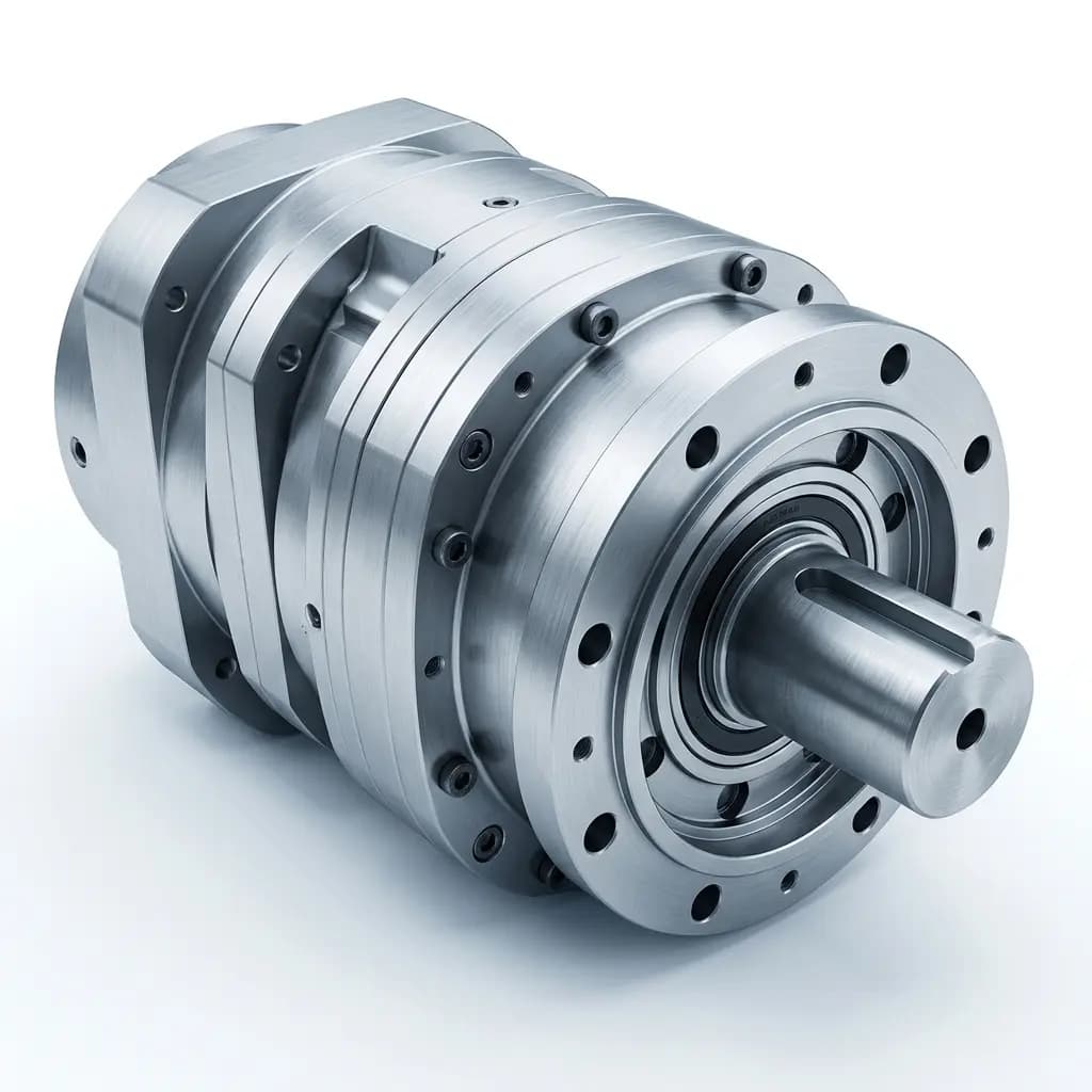
Thermal Management and Duty Cycle Sizing: The Hidden Killers
A gearbox rated for 50Nm will destroy itself at 30Nm if you run it 24/7 without cooling. Here is how to properly size reducers for S1 continuous vs S5 intermittent duty.
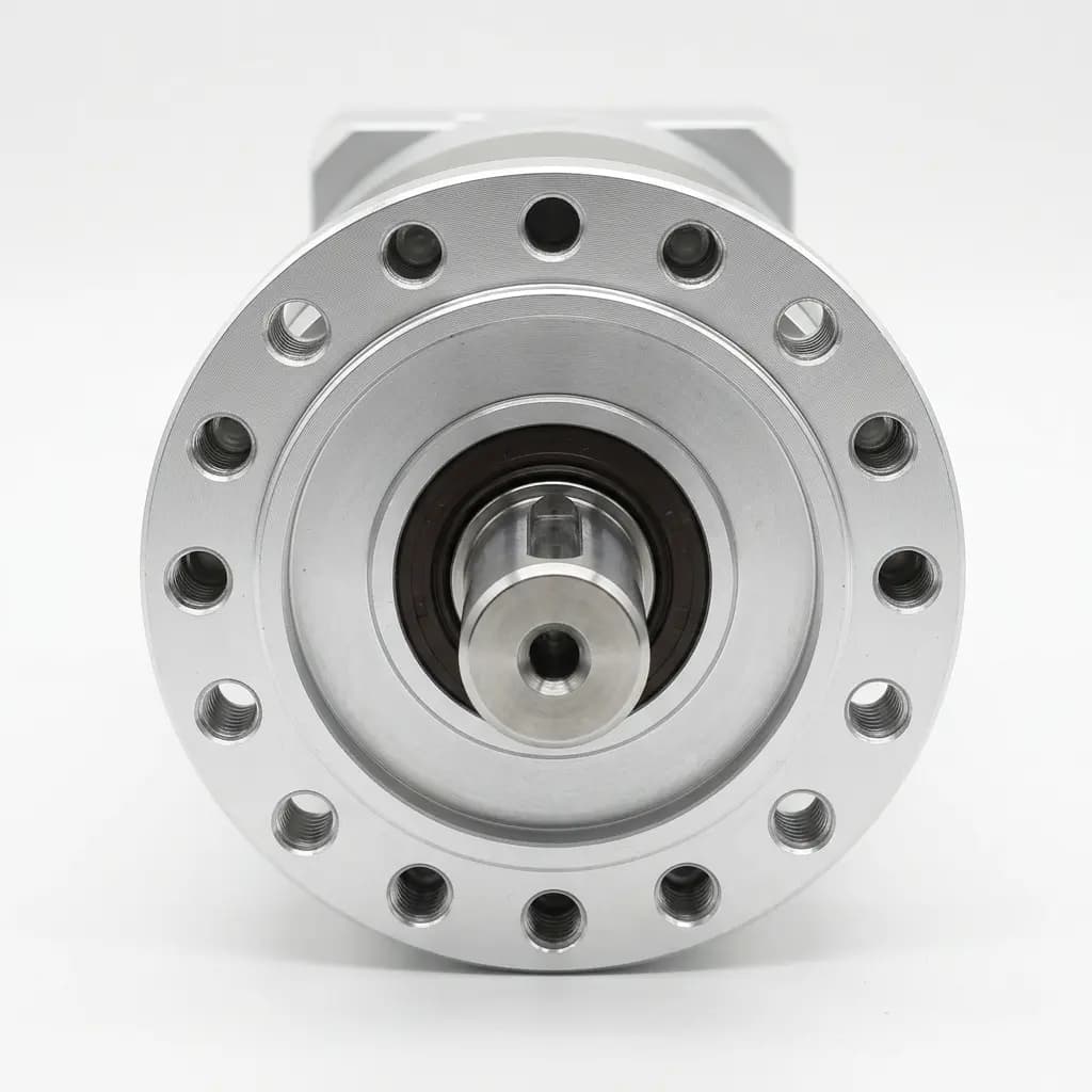
2026-W21 Industrial Update: Documentation Proof Now Controls Low-Backlash Reducer Substitution Risk
2026-W21 low-backlash reducer update for US, EU, and APAC: HTS corrections, CBAM documentation, and servo/stepper retest gates to reduce substitution risk.