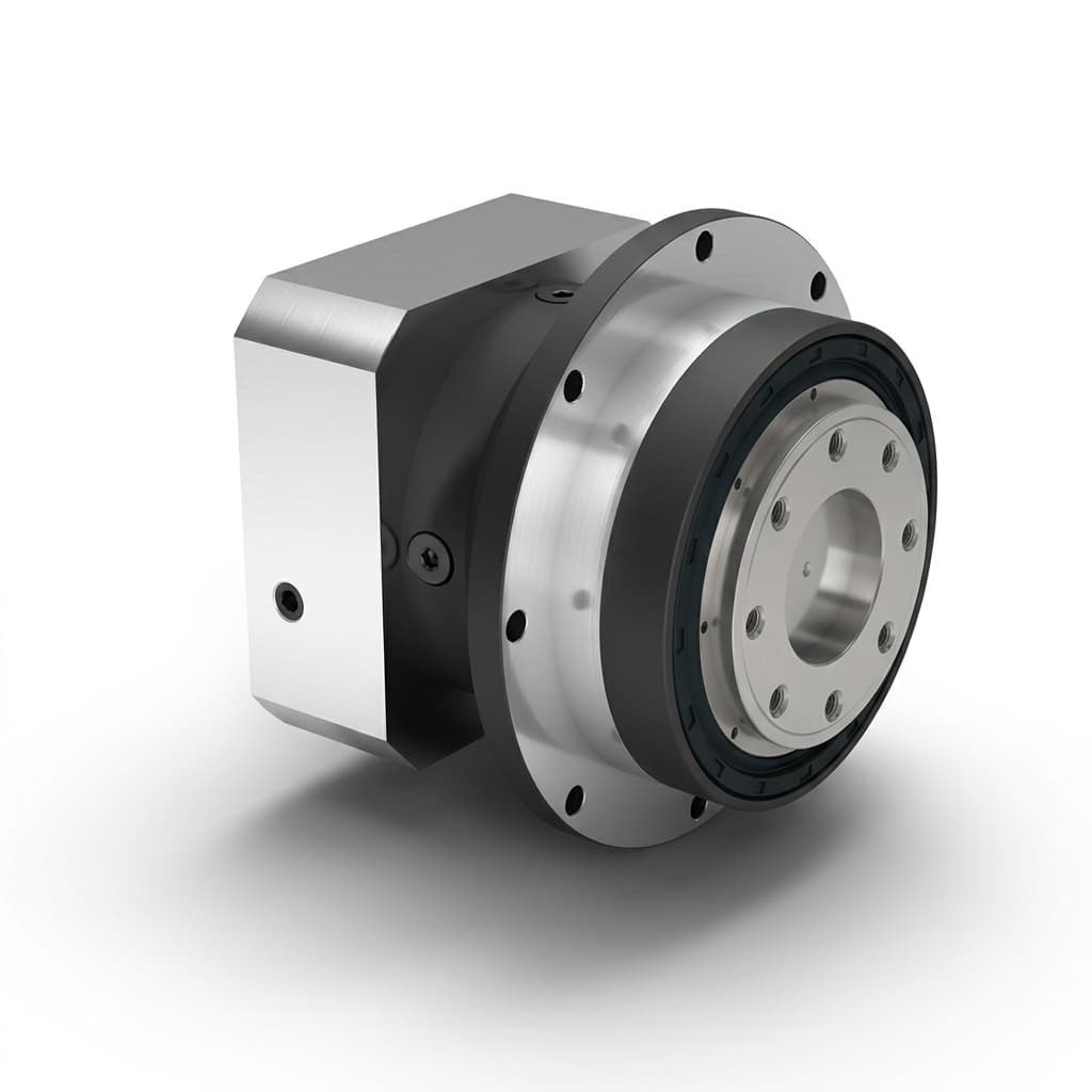
Planetary Gearbox Radial and Axial Load Sizing: Overhung Loads, Bending Moments, and L10h Bearing Life
Size planetary gearbox radial and axial loads using overhang, belt tension, bending moments, and L10h bearing life. Prepare your load data for an RFQ review.
Engineering Takeaway: Planetary gearbox radial and axial load sizing starts with the force at its actual application point, not output torque alone. Resolve belt tension or gear-mesh forces, calculate bearing reactions and bending moments, then check dynamic life and peak static loads separately. With speed and other conditions unchanged, a 25% increase in equivalent dynamic load leaves a ball bearing with 1 / 1.25³ = 51.2% of its basic rating life.
Published: November 2, 2026. Content reviewed: November 2, 2026. Written for mechanical engineers and procurement teams selecting low backlash gearboxes globally; SI units are used throughout.
Scope and limitations: This guide covers output-bearing screening for industrial servo and stepper planetary gearboxes driving pulleys, pinions, conveyors, indexers, and AGV wheels. Numerical examples are illustrative calculations, not measured field results or product ratings. Final selection needs the manufacturer's bearing arrangement, load envelope, lubricant conditions, and application approval. It does not establish whole-gearbox service life, safety certification, or shock survival.
Already sizing an axis with high side loads? Request an application review with your pulley geometry and load cycle, or prepare the inputs using the steps below.
1. The Overhung Load Trap in Servo Gearbox Sizing
Nominal output torque, reduction ratio, and torsional backlash are necessary selection inputs. They do not establish output-bearing capacity or positioning accuracy under side load. A low-backlash gearbox can still deflect or suffer bearing fatigue if its pulley is mounted far from the bearing support.
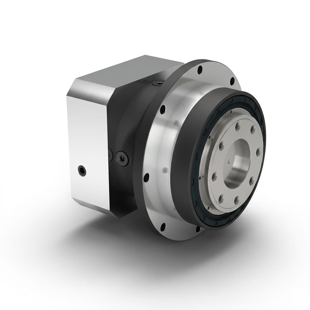
A flange output can shorten the load path when the driven component mounts close to its face. The image does not establish the internal bearing type or a certified load capacity.
Consider a hypothetical datasheet allowing a 2,400 N radial load and an axis needing 1,100 N tangential belt force. Dividing these values does not establish a safety margin: belt pull includes both span tensions, and the allowable load depends on its reference position, speed, and required life. Ask for those conditions before comparing the figures.
Three questions prevent this mismatch:
- Position: Where is the force measured relative to the shaft shoulder and bearing centers?
- Force: What are the tight-side and slack-side belt tensions, including installation tension and acceleration?
- Life: What equivalent load and speed spectrum must each output bearing withstand?
2. Mechanical Anatomy: Radial Load, Bending Moments & Bearing Reactions
The schematic shows a simplified two-support shaft under one radial force. It is not a gearbox cross-section or a scale drawing, and it does not resolve axial load sharing, preload, or internal gear-mesh forces.
The Lever Arm Effect
For a downward external radial load F_r, the front support reaction acts upward and the rear reaction downward. The following equations give their magnitudes:
F_B1 = F_r × (H_B + z_0 + x) / H_BF_B2 = F_r × (z_0 + x) / H_B
Here x is the distance from the shaft shoulder to the load plane, z_0 is the distance from the front bearing center to that shoulder, and H_B is the bearing-center span. Use the same length unit for all three. The balance is F_B1 − F_B2 = F_r.
Increasing x increases both reactions. These are external-load contributions in a statically determinate model; the supplier must add internal forces and use the actual bearing arrangement. Axial reaction sharing cannot be inferred from this radial diagram.
3. First-Principles Calculation: Step-by-Step
Step 1: Calculate Nominal Tangential Force
For output torque T_2 in N·m and pitch diameter d_p in meters:
F_t = 2 × T_2 / d_p
Calculate this for each operating segment, including acceleration and deceleration. Peak torque alone does not describe fatigue duty; nominal torque alone does not describe emergency-stop loads.
Step 2: Resolve the Actual Shaft Load
For a belt drive, F_t = T_tight − T_slack. The shaft experiences the vector sum of the forces exerted by both spans. For approximately parallel spans pulling in the same direction, F_r ≈ T_tight + T_slack. Installation tension can therefore produce substantial radial load even at zero transmitted torque.
A multiplier F_r = f_z × F_t is usable only when the belt or gearbox manufacturer specifies its conditions. A universal factor of 1.25 cannot replace belt tension data.
| Drive element | Load calculation input | Selection check |
|---|---|---|
| Synchronous / timing belt | Tight/slack span tensions, directions, and installation tension | Check stopped, accelerating, and running loads; do not assume a universal multiplier |
| Spur pinion | Tangential force and pressure angle α | Separating force F_sep = F_t × tan α; resultant transverse load F_t / cos α |
| Helical pinion / rack | Tangential force, transverse pressure angle α_t, and helix angle β | Resolve transverse forces and axial thrust F_a = F_t × tan β separately |
| Roller chain sprocket | Tight/slack strand forces and strand directions | Include tensioning, polygon action, and impact conditions from the drive supplier |
| V-belt | Belt count, installed tension, wrap, and span directions | Use belt-supplier tension calculations and the resultant shaft pull |
| Flat belt | Installed tension, wrap, traction conditions, and span directions | Evaluate both span forces; torque alone cannot establish bearing load |
These are force-resolution inputs, not standardized gearbox capacity ratings. For helical gears, use the specified angle convention and direction of thrust, including reversals.
Step 3: Check Position-Dependent Allowable Radial Load
Catalog reference conditions vary by model. Obtain the rated load position, output speed, rating life, axial-load combination, and any shaft-strength limit. Do not assume all catalogs use half the shaft length, 100 rpm, or 20,000 hours.
A constant-moment screening estimate about the front bearing is:
F_screen(x) = F_ref × (z_0 + x_ref) / (z_0 + x)
This keeps the radial moment constant; it is not a universal bearing-life derating rule. In the two-support model above, a front-bearing-reaction limit would instead scale with (H_B + z_0 + x_ref) / (H_B + z_0 + x). The limiting bearing, shaft stress, and allowable combined loads must be established by the manufacturer. Do not uprate a catalog value without approval.
Illustrative Numerical Example: Moving the Pulley
Assume F_ref = 1,800 N, usable shaft length L = 40 mm, reference position x_ref = L/2 = 20 mm, and a supplied bearing offset z_0 = 24 mm. These are hypothetical inputs, not ratings for a frame size or product on this site.
- At
x = 10 mm:F_screen = 1,800 × 44 / 34 ≈ 2,329 N. - At
x = 35 mm:F_screen = 1,800 × 44 / 59 ≈ 1,342 N.
The second estimate is 42.4% below the first under the constant-moment assumption. It does not demonstrate a 42.4% change in certified capacity. The 2,329 N result particularly requires supplier approval because it exceeds the reference rating.
Step 4: Verify Tilting Moment and Combined Loads
Use consistent units. With forces in N and all distances in mm, a conservative sum of bending-moment magnitudes about the front bearing, in N·m, is:
M_screen = [F_r × (x + z_0) + |F_a × y|] / 1,000
Here y is the eccentricity of the axial force relative to the shaft centerline; a concentric axial force has y = 0 but still loads the bearings axially. Resolve moment vectors when directions are known. For F_r = 1,000 N, x = 35 mm, z_0 = 24 mm, and concentric thrust, the radial moment is 59 N·m.
Compare against an allowable moment expressed about the same reference plane. Separately passing radial, axial, and moment maxima does not establish acceptance under simultaneous loads: request the combined-load envelope and verify both thrust directions. Include shaft stress, deflection, mounting bolts, and hub fit where relevant.
Send the force directions, load-plane dimensions, and duty cycle for a model-specific load review before releasing the gearbox purchase order.
4. Bearing Fatigue Life (L10h) and the Cubic Penalty
ISO 281:2007 defines basic and modified rolling-bearing rating life. For constant bearing speed n in rpm and constant equivalent dynamic load P, basic rating life in hours is:
L10h = [1,000,000 / (60 × n)] × (C / P)^p
Cis the basic dynamic load rating of the bearing being assessed, not the gearbox's catalog allowable radial load.Pis that bearing's equivalent dynamic load, calculated from its bearing-level radial and axial loads. Use manufacturer values forX,Y, and any threshold determining when a relation such asP = X × F_rad,b + Y × F_ax,bapplies.p = 3for ball bearings andp = 10/3for roller bearings.L10hcorresponds to 90% reliability for a population of comparable bearings under the stated conditions. It is not a guaranteed replacement interval for an individual gearbox.
Modified life is a separate result: Lnmh = a_1 × a_ISO × L10h, where a_1 accounts for reliability and a_ISO accounts for lubrication, contamination, and fatigue-load conditions. Do not silently include a_ISO in a result labeled basic L10h. ISO 281 does not cover wear, corrosion, or electrical erosion.
Variable Loads and Speed
For discrete rotating segments using the same bearing and life exponent, a basic fatigue screening equivalent is:
P_eq = [Σ(P_i^p × |n_i| × t_i) / Σ(|n_i| × t_i)]^(1/p)
Use n_eq = Σ(|n_i| × t_i) / Σ(t_i) with the same time basis. Absolute speed counts revolutions in both directions; a simple arithmetic mean of loads is unsuitable. Stationary holds, small-angle oscillation, preload, and changing lubrication need separate supplier assessment; a zero-revolution segment is not evidence of zero damage.
The Exponential Sensitivity of Bearing Life
With bearing rating, speed, and other conditions unchanged, L_new / L_old = (P_old / P_new)^p. The table is reproduced directly from that relation; the 20,000-hour baseline is an example, not a catalog promise.
| Equivalent load ratio | Ball-bearing remaining life (p = 3) | Roller-bearing remaining life (p = 10/3) | Ball-bearing life if baseline is 20,000 h |
|---|---|---|---|
| 1.00× | 100.0% | 100.0% | 20,000 h |
| 1.10× | 75.1% | 72.8% | 15,026 h |
| 1.20× | 57.9% | 54.5% | 11,574 h |
| 1.25× | 51.2% | 47.5% | 10,240 h |
| 1.40× | 36.4% | 32.6% | 7,289 h |
| 1.50× | 29.6% | 25.9% | 5,926 h |
| 2.00× | 12.5% | 9.9% | 2,500 h |
These ratios describe calculated fatigue life, not field-failure percentages. If temperature, lubricant, or bearing load sharing also changes, recalculate those effects rather than applying this ratio alone.
5. Architectural Comparison: Output Bearing Configurations
Bearing type helps shortlist a design, but no universal capacity or stiffness multiplier applies across different sizes, preloads, and housings.
| Bearing architecture | Radial / axial load considerations | Moment and integration considerations | Procurement evidence to request |
|---|---|---|---|
| Dual deep-groove ball bearings | Radial capability and limited axial capability depend on the actual bearings | Span, clearance, and shaft stiffness govern overhung response | Bearing part numbers, axial limit, and load-position curve |
| Paired angular-contact ball bearings | Combined loading and thrust directions depend on arrangement and preload | Back-to-back and face-to-face arrangements differ in moment response | Pair arrangement, preload, speed limit, and combined-load data |
| Paired tapered-roller bearings | Can support combined radial and axial forces in a suitable arrangement | Preload, friction, heat, and bearing spacing require verification | Thermal assumptions, preload method, and life calculation |
| Cross-roller bearing flange output | Combined-load capability is specific to the selected bearing | Mounting flatness and bolt stiffness affect achieved rigidity | Load envelope, mounting tolerances, and moment rigidity |
| Flange output with another bearing arrangement | Flange geometry alone does not identify the bearing capacity | A short attachment can reduce overhang; actual load plane still matters | Section drawing, bearing arrangement, and reference plane |
| External supported driven shaft | Can divert external loads away from gearbox output bearings | Alignment and coupling forces remain; extra bearings can overconstrain an assembly | Support layout, coupling reactions, and residual gearbox loads |
When to Choose a Flange Output
Our flange vs shaft output guide helps compare interfaces. A flange can reduce the distance to the load plane when a pulley or pinion mounts close to its face. It does not automatically increase torsional stiffness by a fixed factor or eliminate the load moment.
ISO 9409-1:2004 standardizes circular mechanical-interface dimensions, designation, and marking. It does not assign load-carrying capacity. Ask for the actual bearing ratings and attachment geometry even when the bolt pattern matches.
6. Sourcing & Engineering Checklist: Verifying Overhung Loads Before Ordering
Before issuing an RFQ or purchase order:
- Load position: Dimension the shoulder, bearing reference plane, and pulley or pinion force plane in CAD.
- Drive forces: Provide installed belt tension and both span forces/directions, or the gear/chain load calculation.
- Reference conditions: Obtain the supplier's rated position, speed, life basis, and shaft-strength limits.
- Combined loads: Verify radial force, axial thrust in both directions, and bending moment together.
- Target life: Specify the required basic or modified life and reliability, rather than writing only “long life.”
- Duty spectrum: List torque, load, speed, duration, reversals, and stationary holds for each cycle segment.
- Peak/static check: Include acceleration, emergency stops, and impacts; request static safety-factor confirmation separately from fatigue life.
- Bearing arrangement: Obtain the bearing type, span, preload, and the supplier's calculation assumptions.
- Lubrication and temperature: Verify operating viscosity, contamination controls, and thermal limits using the thermal sizing guide.
- Second-source approval: Compare interfaces and the complete load envelope using the second-sourcing framework, and retain dated application approval.
7. Frequently Asked Questions (FAQ)
Can a larger pulley solve excessive radial load?
At fixed output torque, increasing pitch diameter reduces tangential force through F_t = 2 × T_2 / d_p. Belt installation tension may still dominate the shaft load. For a specified linear axis force, torque must increase with pulley radius, so a larger pulley does not automatically reduce belt pull. Recheck speed ratio, travel per revolution, overhang, and pulley inertia. The relation J ∝ d⁴ applies only to a uniform solid disk of fixed width and material, not every pulley design.
Why did the gearbox leak after we tightened the timing belt?
Excess tension can increase shaft deflection and disturb seal contact. Leakage can also arise from seal damage, temperature, lubricant condition, or installation errors. Check measured belt tension, shaft runout, alignment, and the seal maker's speed-dependent limits; there is no universal runout or angular-deflection threshold for every gearbox seal.
How does operating temperature affect bearing fatigue life?
Temperature changes lubricant viscosity and therefore the lubrication condition used in modified-life calculations. The effect depends on lubricant grade, bearing speed and size, contamination, and temperature at the bearing. There is no universal 70°C boundary or fixed percentage loss of life. Confirm lubricant viscosity at operating temperature and distinguish modified life from basic L10h.
What is the difference between static and dynamic load ratings?
ISO 76:2006 addresses basic static load rating C_0 and equivalent static load P_0; static safety is commonly assessed through s_0 = C_0 / P_0 using the manufacturer's required factor. ISO 281 addresses dynamic rating C and fatigue life during rotation. Neither bearing rating can be substituted directly for a gearbox catalog's allowable shaft load. Check transient peak loads and manufacturer shaft limits as well as fatigue duty.
When should I add an external supported shaft?
Consider external bearings when practical gearbox sizes cannot satisfy the combined-load envelope, when the load plane is far from the output support, or when shaft deflection compromises belt tracking or sealing. There is no universal overhang-to-shaft-length trigger. Design the load path and coupling together: external supports can carry most side load, but misalignment and coupling stiffness can still transmit residual forces and moments into the gearbox.
8. Primary Sources & Engineering References
Reference identities checked for this November 2, 2026 content review. Public ISO abstracts establish the standards' scope; use the applicable full standard and manufacturer bearing data for an approval calculation. The worked examples above are transparent analytical illustrations, not third-party test results.
- ISO 281:2007 — Rolling bearings: Dynamic load ratings and rating life. Basis for distinguishing basic rating life at 90% reliability from modified life. It does not establish whole-gearbox durability or cover all damage mechanisms.
- ISO 76:2006 — Rolling bearings: Static load ratings. Scope covers basic static ratings, equivalent static loads, and static safety-factor guidance. Request manufacturer assessment for unusual load distribution, preload, or alignment conditions.
- ISO 9409-1:2004 — Manipulating industrial robots: Mechanical interfaces, Part 1: Plates. Defines interface dimensions and identification; explicitly does not correlate interface sizes with load-carrying ranges.
Need Application Engineering Verification for Your Drive Axis?
Contact the LowBacklashGearbox engineering desk with your motor model, torque/speed cycle, pulley pitch diameter, belt tensions, overhang dimension, axial-force direction, and target bearing life. Include a CAD layout where available. Request a model-specific combined-load assessment, stated life assumptions, and a dated quotation before placing the order.
Author

Categories
More Posts
How to Safely Second-Source and Cross-Reference Low Backlash Planetary Gearboxes
Validate dimensions, torque, stiffness, duty cycle, and supplier risk before approving a second-source low backlash planetary gearbox replacement in 2026.
Specifying Low Backlash Gearboxes for AGV and AMR Wheel Drives
Choose low backlash gearboxes for AGV/AMR wheel drives with a 2026 checklist for radial loads, shock ratings, bearings, backlash, and RFQ review steps.
The Hidden Cost of Over-Specifying Backlash: A Procurement Guide
A practical July 2026 checklist for deciding when <=1 arc-min backlash is justified, when 3-8 arc-min is enough, and what evidence procurement should request before approving a premium gearbox.